


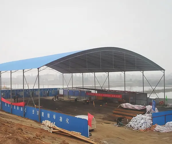
The main characteristics of membrane structure steel structure include "light transmission," "energy saving," "acoustic effects," "durability," and "design." Membrane structure steel structures are lightweight, ...
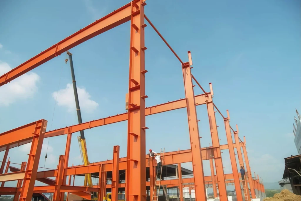
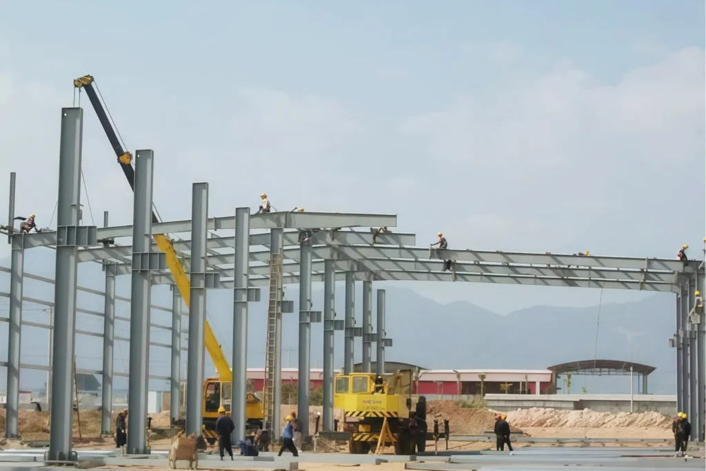
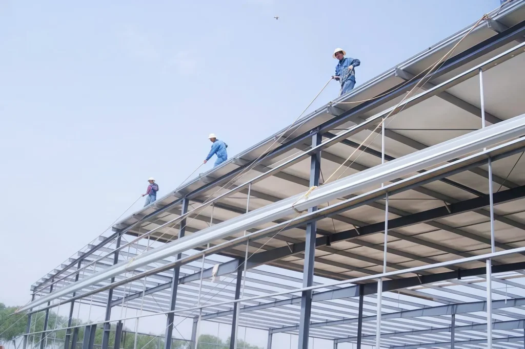
After completing the preliminary manufacturing and processing, the steel structure enters the installation phase. Xingyuanyi follows the standard process in the installation of steel structure buildings: foundation construction—embedding of anchor bolts—hoisting of steel columns—installation of steel beams—installation of purlins and horizontal supports—installation of wall panels—installation of the roofing system—final acceptance.

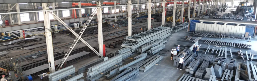
The installation projects we undertake include: steel structure workshops, steel structure platforms, steel structure houses, steel structure canopies, roof covering projects, steel structure additions and renovations, steel structure glass houses, mobile houses, as well as multi-story steel structure buildings, etc.
XinYuanYi is equipped with professional installation equipment, including: steel structure hoisting machines, cutting machines, electric welding machines, hand drills, and various other advanced tools.
The company has an experienced installation team, with more than 200 professional installation personnel, all of whom have solid experience in steel structure installation.
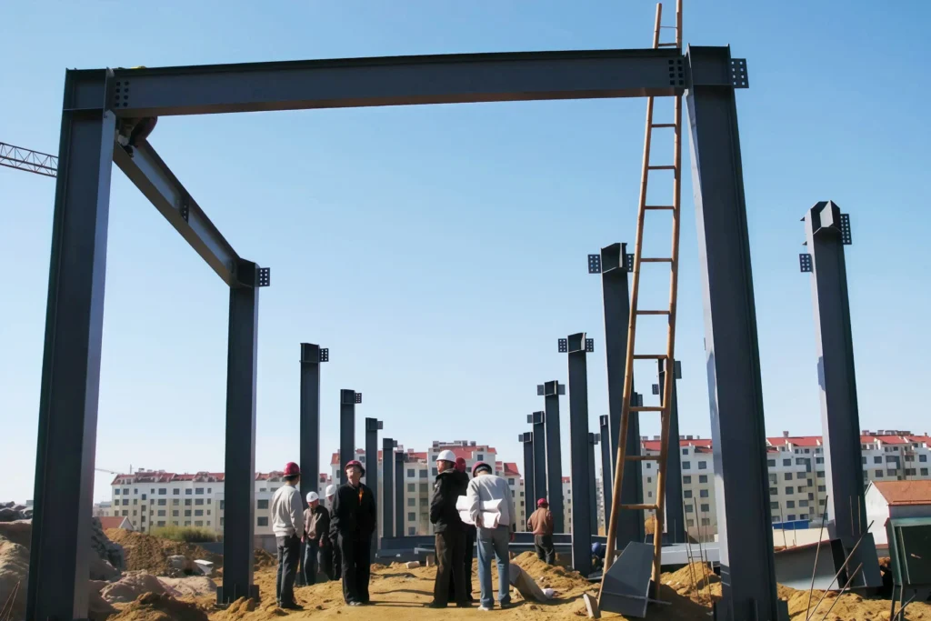
During the installation process, we strictly implement the construction organization design, strengthen on-site management, continuously improve the skill level and safety awareness of construction personnel, and ensure project quality and construction safety.
1 Scope
This technical standard is applicable to the assembly and installation construction of steel structure engineering for general industrial and civil buildings.
2 Construction Preparation
2.1 Equipment and Main Tools
2.2 Materials and Semi-finished Products
2.3 Operating Conditions
3 Operating Processes
3.1 Process Flow
Job preparation → Component installation → Connection and fixation → Inspection and acceptance
3.2 Assembly of Steel Trusses (Steel Skylight Frames)
3.3 Steel Column Assembly
3.4 Steel Beam Assembly
3.5 Assembly of Spatial Arch Trusses
The elevation positioning of the string rod can be controlled using the water pipe communication method.
Process flowIt seems that there is no content provided for translation. Please provide the text you would like me to translate into English.
Body frame manufacturing → Overall assembly positioning → Calibration inspection → Joint welding → UT testing → Post-welding calibration → Coating → Final inspection
Select appropriate lifting equipment and establish a horizontal assembly platform.
The frame is used for truss assembly after acceptance.
During assembly, the deformation after welding is controlled by restraining nodes through the tire tooling.
The butt joint of the steel pipe uses a liner pipe groove form, and the gap is adjusted by a tensioner.
3.6 Installation of Steel Columns
3.6.1 Types of Steel Columns
3.6.2 Selection of Lifting Points
The position of the lifting point should be determined comprehensively based on the shape, section, length of the steel column, and the performance of the lifting equipment.
3.6.3 Lifting Method
For large steel columns in heavy-duty workshops, single, double, or triple machines can be used for lifting based on the lifting equipment and site conditions.
3.6.4 Installation of Light Steel Structure Steel Columns
3.6.5 Steel Column Correction
The calibration content includes: column base elevation, longitudinal and transverse cross lines, and column verticality.
Table 1 Foundation Bolt Tightening Force
| Bolt diameter (mm) | Tightening axial force (kN) |
|---|---|
| 30 | 60 |
| 36 | 90 |
| 42 | 150 |
| 48 | 160 |
| 56 | 240 |
| 64 | 300 |
3.7 Steel frame installation
3.7.1 Lifting Reinforcement
The lateral stiffness of the steel frame is poor and must be reinforced before hoisting.
3.7.2 Binding Requirements
The binding point must be set atAt the roof truss nodeTo prevent bending deformation of components at the lifting points.
3.7.3 Positioning and Fixing
3.7.4 Combined Lifting
To reduce high-altitude operations, the skylight frame can be pre-assembled on the roof truss at ground level, ensuring that the skylight frame is positioned between the two lifting slings during binding to guarantee overall stability (see "Manual" Figures 9-66, 9-67).
3.7.5 Verticality Correction
Theodolite methodPlace the theodolite at the top of the column, with a horizontal distance a from the axis, and set a corresponding point on the opposite column. Measure a distance a from the center line of the truss to ensure that the three points are aligned to ensure verticality (refer to "Manual" Figure 9-67).
Plumb bob method: Pull a long steel wire along the lower chord side under the truss, project the centerline of the upper chord to the same distance measuring scale, and correct it with a plumb bob.
3.8 Steel Beam Installation
3.8.1 Installation of Steel Crane Girders
1. Lifting methods
Determine the best方案综合 based on the weight of the crane beam, the crane capacity, site conditions, and construction schedule requirements.
2. Correction
The calibration content includes elevation, longitudinal and lateral axes (straightness and track gauge), and verticality.
3. Allowable deviation
3.8.2 Installation of Lightweight Steel Structure Inclined Beams
1. Lifting methods
The span of the portal frame diagonal beams is large, and the lateral stiffness is small. To ensure safety and quality and improve efficiency, maximum assembly should be done on the ground, and the entire structure should be lifted and positioned.
2. Lifting Method
3. Selection of Lifting Points
4.梁柱连接 4. Beam-column connection
5. Allowable deviation
The permissible deviations for the installation of portal frame light steel structure houses shall be executed in accordance with the national standard "Quality Acceptance Specifications for Steel Structure Engineering Construction" GB50205-2001.
3.8.3 Installation of Steel Beams in High-rise and Super High-rise Steel Structures
1. Special tooling
2. Installation Sequence
3. Measurement and Welding Control
4. Installation of secondary beams
5. Control of Levelness
If the level exceeds the standard, the main reason is the positioning of the connection plate or the error of the screw hole, measures can be taken.Replace the connection plate.orRe-drilling after filling the weld hole.Method handling.
The allowable deviation for levelness at both ends of the same beam is(L/1000) + 3, and must not exceed 10mm.
3.8.4 Installation Sequence of Portal Steel Frames
4 Quality Standards
4.1 Main Control Project
All measuring instruments used during the installation process must be inspected and verified to be qualified by the metrology department before they can be used.
4.1.2 The measuring tools used for the fabrication, installation, acceptance of steel structures, and civil construction should be calibrated according to the same standard and maintained at the same accuracy level.
4.1.3 The positioning axis lines of the building, the foundation axis lines, elevations, the specifications of the anchor bolts, and their fastening must comply with design requirements.
4.1.4 When the basic top surface is directly used as the bearing surface for columns or when embedded steel plates/bearings are used as the bearing surface, the allowable deviation of the bearing surface relative to the position of the anchor bolts (anchor bolts) should comply withTable 2Requirements.
Table 2 Allowable deviations for support surfaces and anchor bolt (foundation bolt) positions (mm)
| Project | Allowable deviation |
|---|---|
| Bearing surface | |
| Elevation | ±3.0 |
| Levelness | L/1000 |
| Anchor bolts | |
| Bolt center offset | 5.0 |
| Reserved hole center offset | 10.0 |
4.1.5 When using seat paste pads, the allowable deviation should comply withTable 3Regulation.
Table 3 Allowable Deviations of the Grouting Pad Plate (mm)
| Project | Allowable deviation |
|---|---|
| Top surface elevation | 0.0, -3.0 |
| Levelness | L/1000 |
| Location | 20.0 |
4.1.6 When using a cup mouth foundation, the allowable deviation of the cup mouth dimensions should comply withTable 4Regulation.
Table 4 Allowable Tolerances for Cup Mouth Dimensions (mm)
| Project | Allowable deviation |
|---|---|
| Bottom elevation | 0.0, -5.0 |
| Cup mouth depth H | ±5.0 |
| Verticality of the cup opening | H/100, and should not be greater than 10.0. |
| Location | 10.0 |
4.1.7 In the installation of multi-layer and high-rise steel structures, the positioning axes, column positioning axes, elevation levels, the specifications and locations of anchor bolts, and their fastening should comply with design requirements; where there are no specifications, it should execute according to Table 11.2.1 of the "Code for Acceptance of Construction Quality of Steel Structure Engineering" GB50205-2001.
4.1.8 Deformations and coating detachment caused by the transportation, stacking, and hoisting of steel structures must be corrected and repaired.
4.1.9 The design requirements for the tightly pressed joints are that the contact area should be ≥70%, should be closely fitted, and the maximum edge gap should be ≤0.8mm.
4.1.10 The allowable deviation of verticality and lateral deflection for steel frames (supports), trusses, beams, and compressed members can be found in Table 10.3.3 of the "Code."
4.1.11 The allowable deviation of the overall verticality and overall plane curvature of single-layer steel structures can be found in "Specification" Table 10.3.4.
4.1.12 The allowable deviation for the installation of multi-layer columns can be seen in Table 11.3.2 of the "Specification."
4.1.13 The allowable deviations for the overall verticality and overall planar curvature of multi-story and high-rise steel structures are specified in Table 11.3.5 of the "Specification."
4.1.14 The connection of high-strength bolts with ordinary bolts in multilayer plate stacking should be checked with a test hole device and meet the following requirements:
4.2 General Items
4.2.1 The allowable deviation for pre-assembly is specified in Appendix D, Table D of the "Quality Acceptance Specifications for Steel Structure Engineering Construction" GB50205-2001.
4.2.2 The allowable dimensional deviation for anchor bolts (foundation bolts) is as follows:Table 5It seems that your request may not contain any text to translate. If you provide the text you would like translated, I can assist with that!
Table 5 Allowed Deviations for Anchor Bolt (Foundation Bolt) Dimensions (mm)
| Project | Allowable deviation |
|---|---|
| Exposed length of the bolt | +30.0, 0.0 |
| Thread length | +30.0, 0.0 |
4.2.3 The center lines and elevation reference points for main components such as steel columns should be marked completely.
4.2.4 When steel trusses (or beams) are installed on concrete columns, the deviation of the support center from the positioning axis shall be ≤10mm; when using large concrete roof slabs, the spacing deviation between steel trusses (or beams) shall be ≤10mm.
4.2.5 The allowable deviation for the installation of steel columns can be found in Appendix Table E.0.1 of the "Standards."
4.2.6 The allowable deviation for the installation of steel gantry beams or similar components that directly bear dynamic loads is shown in Appendix Table E.0.2 of the "Code".
4.2.7 Allowable deviations for the installation of secondary components such as purlins and wall brackets are as follows.Table 6It seems that your request may not contain any text to translate. If you provide the text you would like translated, I can assist with that!
Table 6 Allowable Installation Deviations for Secondary Components such as Purlins and Wall Brackets (mm)
| Project | Allowable deviation | Inspection method |
|---|---|---|
| The center of the wall rack column is offset from the positioning axis. | 10.0 | Steel ruler inspection |
| Verticality of wall bracket columns | H/1000, and should not be greater than 10.0. | Theodolite or plumb line + steel measuring tape |
| The curvature height of the wall shelf upright. | H/1000, and should not be greater than 15.0 | Theodolite or plumb line + steel measuring tape |
| Verticality of the wind-resistant truss | h/250, and should not be greater than 15.0 | Plumb line + steel ruler |
| The spacing of purlins and wall beams. | ±5.0 | Steel ruler inspection |
| The curvature height of the purlin. | L/750, and should not be greater than 12.0. | String line + steel tape |
| The deflection of the wall beam is high. | L/750, and it should not be greater than 10.0. | String line + steel tape |
Note: H - height of the wall support column; h - height of the wind-resistant truss; L - length of the purlin or wall beam.
4.2.8 The installation of steel platforms, steel ladders, and railings shall comply with the current national standards "Fixed Steel Vertical Ladders" GB4053.1, "Fixed Steel Inclined Ladders" GB4053.2, "Fixed Protective Railings" GB4053.3, and "Fixed Steel Platforms" GB4053.4. Allowable deviations are as follows:Table 7It seems that your request may not contain any text to translate. If you provide the text you would like translated, I can assist with that!
Table 7 Allowable Deviations for the Installation of Steel Platforms, Steel Ladders, and Guardrails (mm)
| Project | Allowable deviation | Inspection method |
|---|---|---|
| Platform height | ±15.0 | Level instrument inspection |
| Platform beam levelness | L/1000, and should not be greater than 20.0 | Level instrument inspection |
| Platform pillar verticality | H/1000, and should not be greater than 15.0 | Theodolite or plumb line + steel measuring tape |
| The load-bearing platform beam is subject to lateral bending. | L/1000, and should not be greater than 10.0 | String line + steel tape |
| Verticality of the load-bearing platform beam | h/250, and should not be greater than 15.0 | Plumb line + steel ruler |
| Verticality of the elevator shaft | L/1000, and should not be greater than 15.0 | Plumb line + steel ruler |
| Railing height | ±15.0 | Steel ruler inspection |
| Spacing between railing posts | ±15.0 | Steel ruler inspection |
4.2.9 The allowable deviation for the fit gap of on-site weld seams is as follows:Table 8It seems that your request may not contain any text to translate. If you provide the text you would like translated, I can assist with that!
Table 8 Allowable Deviations for Joint Gaps in Field Welds (mm)
| Project | Allowable deviation |
|---|---|
| No gap between the pads. | +3.0, 0.0 |
| There is a gap in the pad. | +3.0, –2.0 |
4.2.10 The surface of the steel structure should be kept clean, and the main surfaces must be free from scars, mud, and other impurities.
4.2.11 The allowable deviations for the installation of multi-layer and high-rise steel structures are provided in Appendix Table E.0.5 of the "Code."
4.2.12 The allowable deviation of the total height of multi-layer and high-rise main structures is shown in Appendix Table E.0.6 of the "Standard."
5 Finished product protection
5.1 When steel structures are stored on-site, the ground should be solid and well-drained; components must be elevated by 200mm and must not be placed directly on the ground.
5.2 During transportation, handling, and lifting of steel structures, reliable reinforcement and protection measures should be implemented to prevent deformation.
6 Quality Issues to Pay Attention To
6.1 The installation of single-layer steel structures should preferably followFirst vertical components, then planar components.In order to control vertical cumulative errors and ensure engineering quality, the sequence is carried out.
6.2 During construction, measures should be taken in a timely manner according to the structural spatial stability.Guy wireTake anti-wind measures to prevent the frame from toppling over.
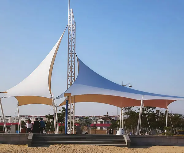
The main characteristics of membrane structure steel structure include "light transmission," "energy saving," "acoustic effects," "durability," and "design." Membrane structure steel structures are lightweight, ...
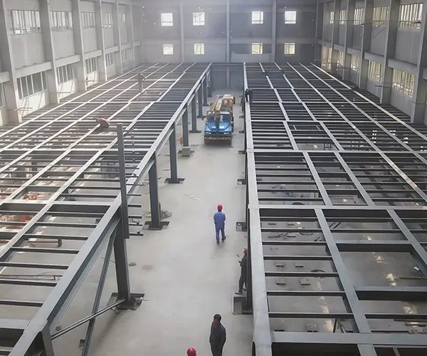
The steel structure platform is also known as a work platform. Modern steel structure platforms have a variety of structural forms and are equipped with a full range of functions. The biggest characteristic of its structure is that it is fully assembled, with flexible design, …
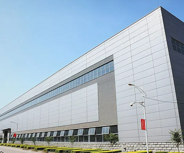
Steel structure exhibition halls are widely used in large exhibitions such as: steel structure car exhibition halls, steel structure 4S stores, steel structure exhibition centers, steel structure service exhibition halls, platform-type steel structures, etc.
The steel structure glass canopy is made of stainless steel or steel materials and laminated tempered glass. The surface of the steel materials is treated with hot-dip galvanizing, fluorocarbon spraying, or electrostatic powder coating, ...
Steel structure roofs have comprehensive advantages such as lightweight, factory manufacturing, quick installation, short construction period, good seismic performance, fast return on investment, and less environmental pollution, compared to reinforced concrete...
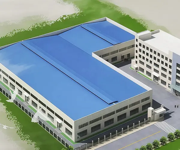
Founded in 2017, located in Hai'an City, Jiangsu Province,
Relying on the advantageous geographical location of the Yangtze River Delta,
Global procurement of raw materials (such as high-strength steel)
Efficient cross-border transportation with the product (only 120 kilometers from Shanghai Port,
Shipping to Southeast Asia takes about 7-15 days, and to the Middle East about 25-30 days.
No. 196 Baidian Road, Baidian Town, Hai'an City, Jiangsu Province
© Copyright 2025 Nantong XinYuanYi Steel Structure Engineering Co.,Ltd. | All Rights Reserved